3D RLC Circuit Phasor Diagram
Circuit Parameters
60 Hz
50 Ω
Component Values
0.1 H
10 μF
Source Voltage
50 V
0°
Circuit Information
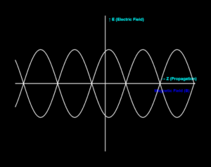
This 3D simulation shows the phasor diagram for a series RLC circuit with:
- Current phasor I (reference, green)
- Resistor voltage VR (red)
- Inductor voltage VL (blue, leads by 90°)
- Capacitor voltage VC (purple, lags by 90°)
- Source voltage V (orange, vector sum)
V = √[VR² + (VL - VC)²] = I × Z
Use the view buttons to see the phasors from different angles.


