Series LCR Circuit Resonance Simulation
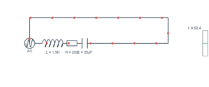
Interactive demonstration of resonance in a series LCR circuit with L=5.0H, C=80µF, R=40Ω, 230V AC source
Current Frequency:
7.96 Hz
Resonance Status:
At Resonance
Circuit Behavior:
Resistive
Simulation Controls
Frequency Control
7.96 Hz
Component Values
40 Ω
5.0 H
80 µF
Animation Control
1.0x
Real-time Calculations
Circuit Parameters
Resonant Frequency (f₀):
7.96 Hz
Current RMS (I):
5.75 A
Impedance (Z):
40.0 Ω
Quality Factor (Q):
6.25
Reactances
Inductive Reactance (XL):
250.0 Ω
Capacitive Reactance (XC):
250.0 Ω
Net Reactance (XL - XC):
0.0 Ω
Phase Angle (φ):
0.0°
Voltage Drops
Source Voltage (V):
230.0 V
Resistor Voltage (VR):
230.0 V
Inductor Voltage (VL):
1437.5 V
Capacitor Voltage (VC):
1437.5 V
Understanding LCR Circuit Resonance
What is Resonance?
At resonance frequency f₀ = 1/(2π√LC), the inductive reactance XL equals the capacitive reactance XC. This makes the circuit purely resistive with minimum impedance.
f₀ = 1/(2π√LC) = 7.96 Hz
Maximum Current at Resonance
When XL = XC, they cancel each other out, leaving only resistance to oppose current flow. This results in maximum current I = V/R.
I_max = V/R = 230V/40Ω = 5.75 A
Voltage Magnification
At resonance, individual voltages across L and C can be much larger than the source voltage. They are 180° out of phase and cancel each other in the phasor sum.
VL = VC = I × XL = 5.75A × 250Ω = 1437.5V
Quality Factor (Q)
Q-factor represents the sharpness of resonance and voltage magnification. Higher Q means sharper resonance peak and higher individual voltages.
Q = XL/R = 250Ω/40Ω = 6.25
Phase Relationships
f < f₀: Capacitive (current leads voltage)
f = f₀: Resistive (current and voltage in phase)
f > f₀: Inductive (current lags voltage)
Phase angle: φ = arctan((XL - XC)/R)
Key Insights
• At resonance, impedance is minimum (Z = R)
• Current is maximum (I = V/R)
• Individual voltages can exceed source voltage
• Total reactive voltage (VL - VC) is zero
• Circuit appears purely resistive
• Current is maximum (I = V/R)
• Individual voltages can exceed source voltage
• Total reactive voltage (VL - VC) is zero
• Circuit appears purely resistive