Mutual Inductance Flux Linkage Simulation
Coil Parameters
Time Parameters
Calculated Results
Change in current (ΔI): 20 A
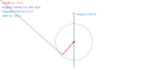
Rate of change of current (dI/dt): 40 A/s
ε = μ × (dI/dt)
Induced EMF (ε): 60 V
ΔΦ = μ × ΔI
Change in flux linkage (ΔΦ): 30 Wb
Explanation
This simulation demonstrates the concept of mutual inductance between two adjacent coils. When the current in one coil changes, it induces an electromotive force (EMF) in the adjacent coil due to their mutual inductance.
The key relationships shown are:
ε = μ × (dI/dt)
Where ε is the induced EMF, μ is the mutual inductance, and dI/dt is the rate of change of current.
ΔΦ = μ × ΔI
Where ΔΦ is the change in flux linkage with the other coil, and ΔI is the change in current.
In this example, with a mutual inductance of 1.5H, a current change from 0A to 20A in 0.5s results in a flux linkage change of 30Wb in the adjacent coil.