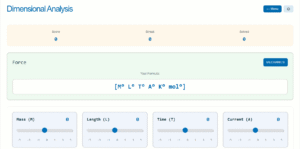
Battery Discharge Circuit Simulation
Interactive demonstration of terminal voltage and internal resistance effects
Real-time Calculations
EMF vs Terminal Voltage
EMF (Electromotive Force) is the maximum voltage the battery can provide when no current flows. Terminal voltage is what you actually measure when the battery is connected to a load and is always less than EMF due to internal resistance.
Internal Resistance Effect
Internal resistance causes a voltage drop inside the battery itself. As current increases, this voltage drop increases, reducing the terminal voltage available to external circuits. This is why batteries provide less voltage under heavy loads.
Key Formulas
Power Distribution
The total power from the battery is distributed between the external resistor (useful power) and the internal resistance (wasted power). Higher internal resistance means more power is wasted inside the battery.