LCR Circuit Resonance
This simulation demonstrates resonance in an LCR circuit as described in Example 7.9, showing how impedance, current, and power vary with frequency.
Example
Question:
Suppose the frequency of the source in the previous example can be varied. (a) What is the frequency at which resonance occurs? (b) Calculate the impedance, the current, and the power dissipated at the resonant condition.
Solution:
(a) Resonance frequency:
\[
\omega_0 = \frac{1}{\sqrt{LC}} = \frac{1}{\sqrt{25.48 \times 10^{-3} \times 796 \times 10^{-6}}} = 222.1~\text{rad/s}
\]
\[
\nu_r = \frac{\omega_0}{2\pi} = \frac{221.1}{2 \times 3.14} = 35.4~\text{Hz}
\]
(b) At resonance, impedance \(Z = R = 3\,\Omega\):
Rms current at resonance:
\[
I = \frac{V}{Z} = \frac{283/\sqrt{2}}{3} = 66.7~\text{A}
\]
Power dissipated:
\[
P = I^2 R = (66.7)^2 \times 3 = 13.35~\text{kW}
\]
Thus, power dissipated at resonance is more than in Example 7.8.
Angular Frequency
ω = 2πν
Impedance (Z)
Z = √(R² + (XL - XC)²)
Current (I)
I = V/Z
Resonant Frequency
νr = 1/(2π√(LC))
Power Dissipated
P = I²R
Quality Factor (Q)
Q = ω0L/R
Explanation (from Example 7.9):
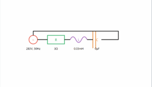
This simulation shows an LCR circuit with R = 3Ω, L = 25.48 mH, and C = 796 μF. At resonance (35.4 Hz):
- Impedance (Z) is minimum and equal to resistance (3Ω)
- Current (I) reaches maximum value (66.7 A)
- Power dissipation is maximum (13.35 kW)
Resonance occurs when XL = XC, causing the imaginary part of impedance to cancel out (ω0 = 1/√(LC)).