NAND Gate Simulation with Waveforms
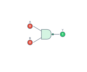
This interactive simulation demonstrates the NAND gate operation with visual schematic and timing diagrams. The NAND gate outputs 0 only when both inputs are 1, otherwise it outputs 1.
NAND Gate Truth Table
| A | B | Y (Output) |
|---|---|---|
| 0 | 0 | 1 |
| 0 | 1 | 1 |
| 1 | 0 | 1 |
| 1 | 1 | 0 |
Current Time: t = 0
Input A: 1
Input B: 1
Output Y: 0